INTRODUCTION
Electronic blind stick is a simple tool that can help a blind person to detect obstacles like walls, tables, stairs, any sleepy liquid on the floor etc without touching them through an alarm system. This reduces the chances of any accident. Also if this blind stick falls down on ground, then an automatic alarm starts ringing so that its owner can easily find it even if he can’t see it. This blind stick is made at very low cost with a very simple circuit.
WORKING
Its working is very simple. It has two main parts:
- Sensors
- Signal Amplifier & Buzzer

Fig:1
Fig:1 shows the block diagram of the complete system. Stick position detector, Liquid dirt detector and IR proximity sensor all of these come under 1st part i.e. sensors. Signal amplifier circuit and Buzzer comes under 2nd part.
Different sensors detect different types of obstacles and generate an electrical signal. Those signals then go to the amplifier circuit that amplifies the signal strength. Output of the amplifier is connected to the buzzer, so that whenever any obstacle is detected by the sensors, the amplified signal from amplifier circuit turns the buzzer on.
COMPONENTS
It can be seen in Fig1 that it has 5 blocks :
- Stick position detector
- Liquid dirt detector
- IR proximity sensor
- Signal amplifier circuit
- Buzzer
Each block with their internal components are described below.
1)Stick Position Detector.
It is a sealed cylinder containing a conductive liquid. The two ends of the cylinder have two terminals as shown below.

Fig:2
This figure shows a stick position detector in vertical position. In this position liquid level is not enough to touch the upper terminal and make a low resistance contact between two terminals. This results in a very high resistance of the detector when it is in vertical position.

Fig:3
But when the detector is in a horizontal position the conductive liquid spreads between the terminals making a low resistance contact between them. This results in a very low resistance when the detector is in a horizontal position.
2)Liquid Dirt Detector
This is a simple arrangement of two conductors separated from each other, attached to the lower end of the stick as shown in fig:4. Terminal resistance of the detector is very high during normal conditions but when it comes in contact with liquid dirt, its terminal resistance becomes very low.

Fir:4
Hence, liquid dirt detector convert the presence or absence of dirt liquid at the end of the stick into low resistance and high resistance of itself respectively.
3)IR Proximity Sensor
IR proximity sensor consists of two parts:
- IR Transmitter
- IR Sensor module
a)IR Transmitter
IR transmitter consists of an astable multivibrator using IC 555. This multivibrator generates a square pulse of particular frequency range that is acceptable by the IR sensor module. The output of the multivibrator is given to the IR LED ( infrared light emitting diode). Infrared is beyond our visual electromagnetic radiation so we can't see the infrared light emitted by IR LED. So, IR LED continuously emits infrared radiation of particular frequency generated by astable multivibrators. Circuit diagram of astable multivibrator with IR LED connected is shown below.

Fig:5
b) IR Sensor Module
IR sensor module is a device that receives infrared light at particular frequency and gives out voltage as output. The output from the IR sensor module is connected to an optocoupler whose output resistance changes as input voltage changes inversely. Hence, the complete setup of the IR sensor module receives infrared light at particular frequency as input and gives out change in resistance as output.
IR sensor modules and IR LED are kept together to form an IR proximity sensor. This setup detects the presence and absence of objects in front of it.

Fig:6
When there is no any object in front of the IR proximity sensor all of the infrared radiation emitted by the IR transmitter is gone as shown in fig:6.
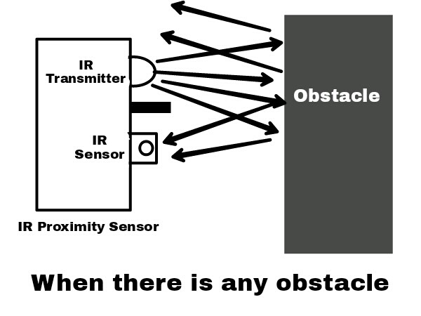
Fig:7
When any obstacle comes in front of it, infrared radiation is reflected back and when it falls back on the IR sensor module the presence of the object is detected.
4)Signal Amplifier Circuit
This circuit consists of an NPN transistor BC-547 connected in base Biased configuration as shown below.

Fig:8
As discussed above output of every sensor used in this system is in the form of change in electrical resistance. As shown in fig:8, the transistor used here works as a switch which turns on when current goes into its base and turns off when there is no any base current. Hence, base current acts as input to this switch. In normal conditions the resistance of the base terminal is very high and So, base current is obtained at that time. If any sensor is actuated by the respective actuating parameters then the resistance of the base terminal path goes down and enough base current is obtained which drives the transistor into saturation mode. Then it can be said that the transistor turns on the buzzer whenever any obstacle is detected by any of the sensors.
5)Buzzer
The output of the signal amplifier circuit is given to the Buzzer as shown in fig:8. The output of the Buzzer is the final output of the complete system in the form of sound that alerts the blind person for the type of obstacle mentioned in this report.
List of required Items with their Amazon link :
Comments
Post a Comment